c) Documented group project and individual contribution
Planning
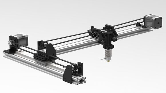
Our group decided to build an 3 axis machine for ploting using a pen. Along the way, we found that there are many people out there doing the same thing. Therefore we decided to divert from the norm and built a 2 axis machine with its platform used as a target practise by placing an object as target to be shot at with a rubbber band gun. The idea is to promote fun and games among children and to let to let them know how a simple XY axis machine can be builded. It is an inspiration taken during carnival in our childhood days. The target would move in a horizontal linear motion while using a air pistol to shoot it down. Shooting Gallery
Design and Conceptualization
We designed the machine with this concept in mind of what it would look like. Simple XY Axis
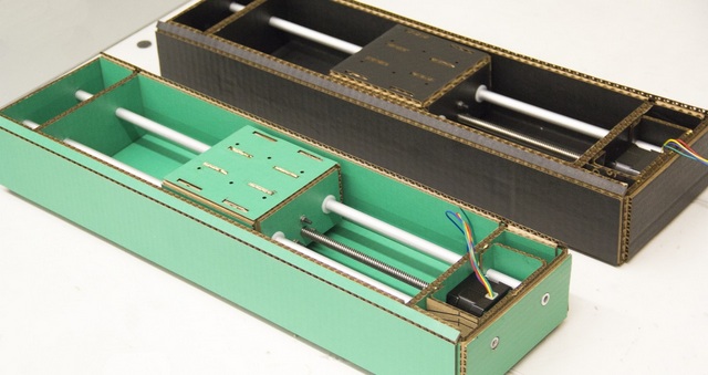
The end product would looked something this Cardboard Structure
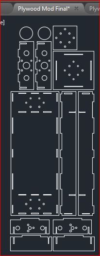
Thankfully, we had help from a fellow course mate; Hendra; who helped us by giving his template to jump start our design progress.
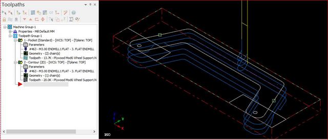
Such that we could used his design and modify it using Autocad to suit our needs. Plywood Mod Final (Right click and save link as)
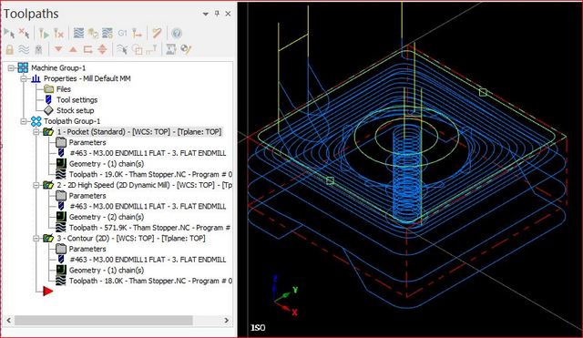
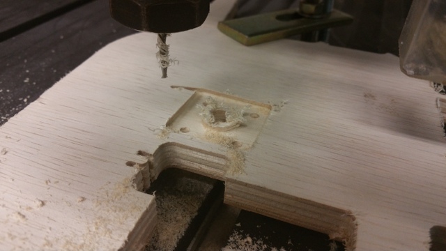
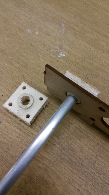
Actual picture of the guide stoppers Routing in Process
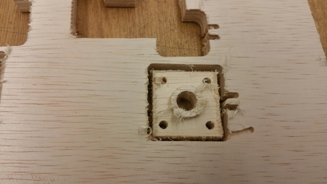
End of Route
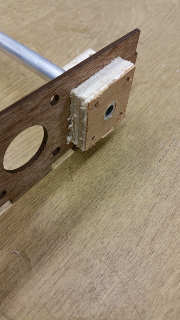
Use of stopper
Use of stopper
Assembly
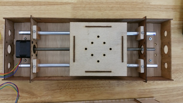
After the all the parts are prepared, its now time to assemble. Assembly of Y axis
The same is done on the X axis.
Testing out
After the assembly, its important to test the motion. Because the aluminium guide might be misaligned and subjected the stepper motor to unnecessary high load and caused the transfer table motion to be impede. Therefore, to avoid this occurrence, we need to manually turn the lead screw to feel friction acting guide rod. If the transfer table is transversing smoothly along the guide rod then its good to go. Manual Turning (Right click and save link as)
My comments
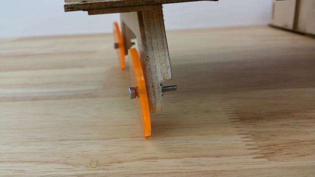
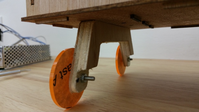
We employed the tactics of press fit construction learned from week 3 on Computer-Controlled Cutting. We encountered a bit of problem when joining the parts at right angles of each other. Firstly, the adjoining top edges of 2 panels could not be flush because the depth of the slots were same. Therefore, to overcome this problem, we kept the depth of a panel slot at 22mm while he other panel slot at 23mm. Secondly, we wanted the stepper motor be easily removed and replaced if it broke down. Therefore, we added slots on the box side panel so that the whole motor and guide rods assembly can be detach from the box easily. Lastly, we added wheels on the far ends of the X axis for better support because it was deflecting badly and stressing its joints connecting to the Y axis.
The wheels could have better improved by adding small bearings to reduce fricition and whobbly between the screws and the arcylic wheels.
The circumference of the wheels could be wider so that a humble "O" ring be added around it to improve stability.
The pen holder could be designed better to hold the pen more securely so that deflection could have drastically reduce to improve accuratey
Click on this link to better understand how to build an cardboard CNC.
Click on this link to find out more details of this modular machine.